BEHAVIOR OF ANCHOR SYSTEMS

In cracked concrete under tension loading
1.1 Anchor load transfer mechanism

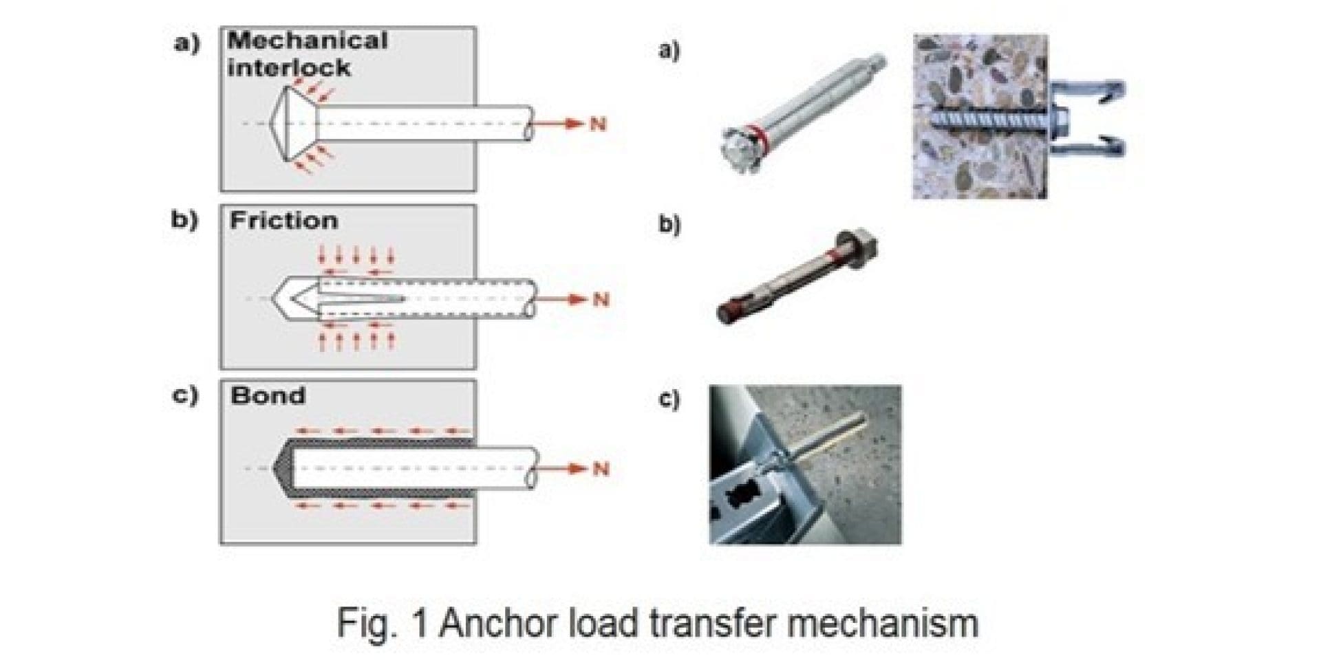
Fasteners transfer applied loads to the base material in various ways (Fig. 1).

Load transfer mechanisms are typically identified as mechanical interlock, friction or bond.

Please enter alternative text here (optional)

Mechanical interlock involves transfer of load by means of bearing interlock between the fastener and the base material. Mechanical interlock is the load transfer mechanism employed by headed anchors, screw anchors (e.g. Hilti HUS), and undercut anchors (e.g. Hilti HDA).


Friction is the load transfer mechanism employed by expansion anchors (e.g. Hilti HSL, Hilti HSA and Hilti HST). During the installation process, an expansion force is generated which leads to the rise to a friction force between the anchor and the sides of the drilled hole. This friction force is in equilibrium with the external tensile force.


In the case of chemical interlock, the tension load is transferred to the base material by means of bond i.e. some combination of adhesion and micro-keying. Chemical interlock is the load transfer mechanism employed by bonded anchors e.g. HIT-HY-200, HVZ.

1.2 Cracked Concrete

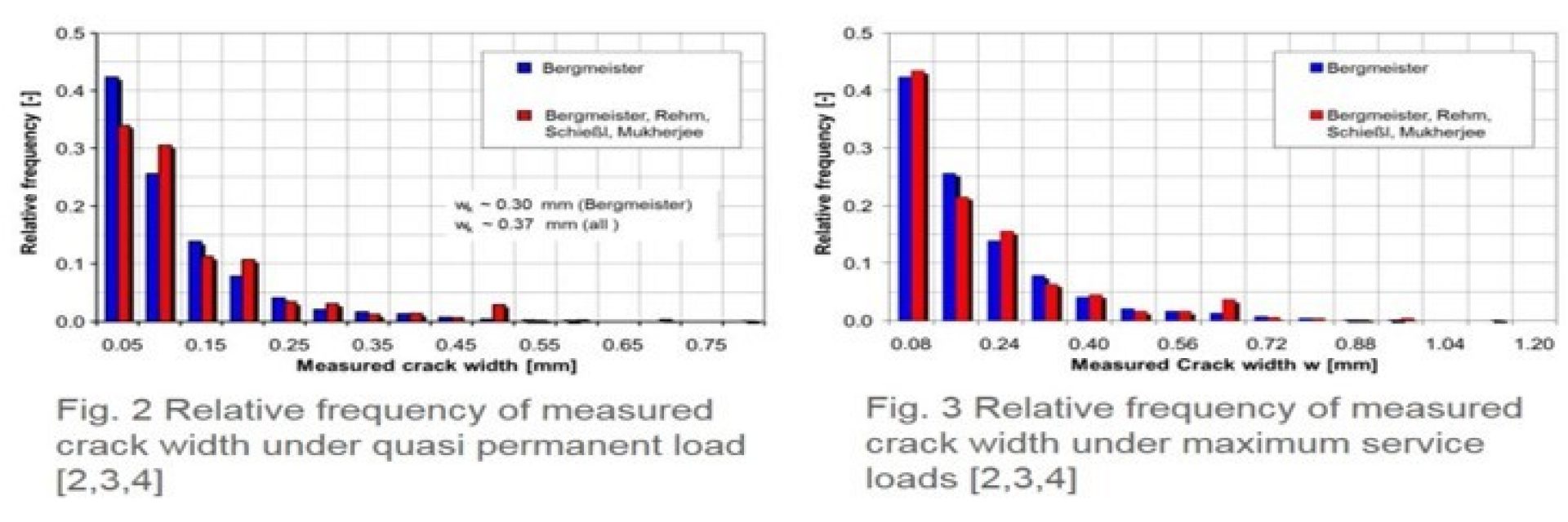
In the design of reinforced concrete flexural or tension components, a cracked tension zone is assumed because concrete possesses relatively low tensile strength, which may be fully or partly used by internal or restraint tensile stresses not taken into account in the design [1] (Fig. 4). Experiences has shown that crack widths resulting from primarily quasi permanent loads (dead loads plus fraction of live loads) do not exceed the value of w95% ~ 0.3mm to 0.4mm [2,3,4] (Fig. 2). These crack widths are generally acknowledged as permissible. Wider cracks are to be expected under maximum permissible service loads, which according to [3] reach w95%~0.5mm to 0.6mm, see Fig. 3 [2,3,4] 

Please enter alternative text here (optional)

It has been observed that when cracks form in a concrete member, there is a relatively high likelihood that they will intersect the anchor location directly or tangentially [1]. This occurs because higher tensile stresses exist around the anchor as a result of: (a) hoop stresses associated with the prestressing and loading of the anchor, (b) possible local flexural stresses resulting from the concentrated load introduced by the anchor and (c) the stress concentration caused by the presence of the anchor hole (notch effect), see Fig. 5 Stress distribution around the anchors as a result of hoop stresses associated with prestressing and loading and stress concentration caused by discontinuity (notch effect). 

Please enter alternative text here (optional)

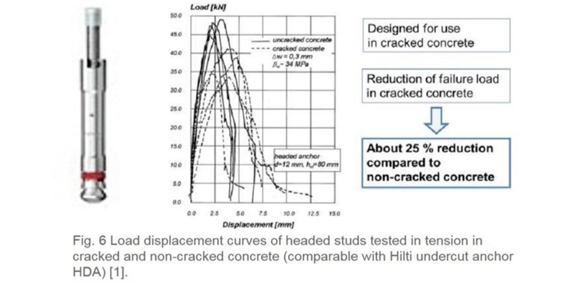
Fig. 6 shows the effect of cracking on anchor performance of headed studs by means of schematically load displacement curves taken from [1] in non-cracked and cracked concrete. Note that this behavior is similar to Hilti undercut anchor HDA which is suitable for cracked concrete applications. Anchor failure is characterized by concrete cone breakout, both cracked and non-cracked concrete. For crack width Dw= 0.3mm general, failure loads of headed studs and Hilti undercut anchor HDA range from 0.5mm to 1.0mm (on average 0.75) times the value in non-cracked concrete. This is based on the fact, that both headed studs and Hilti undercut anchor HDA transfer the applied tensile force to the concrete by means of mechanical interlock (provided by the undercut). 

Please enter alternative text here (optional)

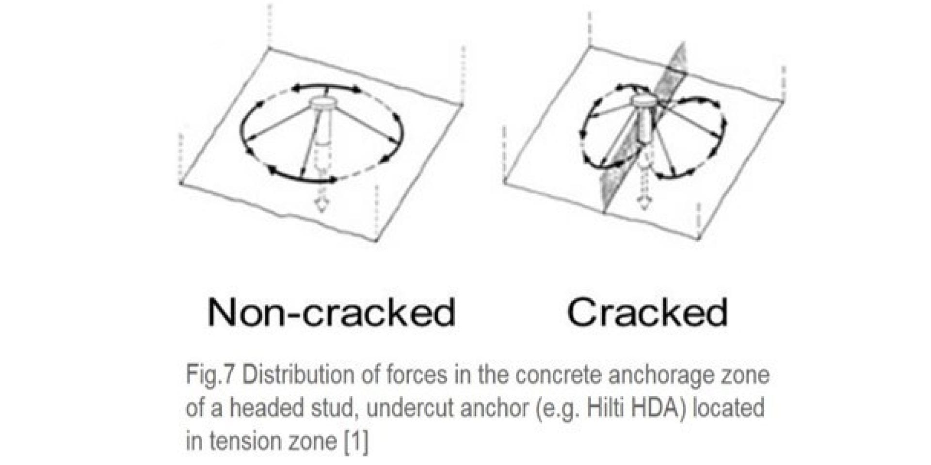
The reduced failure load in cracked concrete must therefore be attributed to the disruption of the stress field associated with cracks (Fig.7) [1]. In non-cracked concrete a tension loaded HDA Hilti undercut anchor generates a rotationally symmetric stress pattern around the anchor as schematically seen in Fig.7 (headed studs). 

If the anchor is located in cracks of sufficient width, the tensile stresses can no longer be transferred across the crack plan and are not rotationally distributed (disturbance of the rotational stress field). This reduces the failure load in case of concrete cone failure up to 25%.


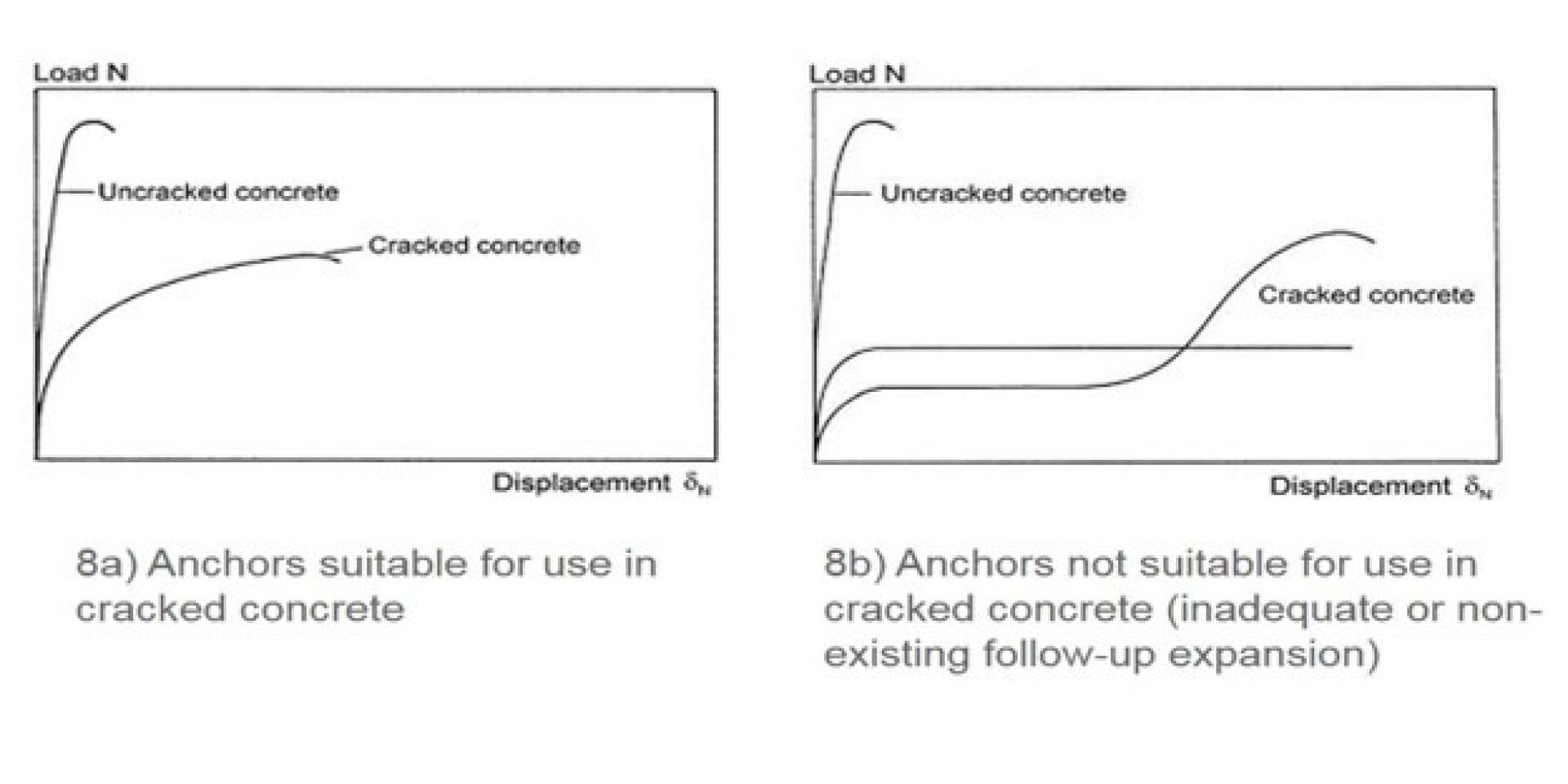
Schematic load displacement curves for tests in non-cracked and cracked concrete conditions associated with a torque controlled expansion anchor (e.g. Hilti HSL, Hilti HST) that is suitable for applications in cracked concrete are shown in Fig. 8a. Anchor failure is characterized by concrete cone breakout in both cracked and non-cracked concrete. 

The effect of cracking on the load displacement behavior and peak load is similar to that observed for headed studs. Torque controlled expansion anchors that are not suitable for applications in cracked concrete (Hilti HSA) can exhibit so called uncontrolled slip when loaded in tension in cracks, since such anchors may not develop follow-up expansion (necessary to reestablish anchorage in crack) or so only after significant displacement (Fig. 8b) [1].

Please enter alternative text here (optional)

In principle bonded anchors exhibit the same basic failure modes as expansion and undercut anchors. However, the performance (bond strength) of bonded anchors is primarily a function of the mortar and the sensitivity to hole cleaning, condition of the borehole (dry, wet and water filled), drilling process (hammer drilled, diamond core drilled), temperature and various other parameters, see [6].


Tests in [6] performed with Hilti HIT-RE 500-SD indicated that if the bond strength of the mortar is high enough and concrete cone failure occurs, the influence of cracks on the failure load is comparable with the influence of cracks on the load displacement behavior of expansion and undercut anchors by means of a reduction of ~25%. 


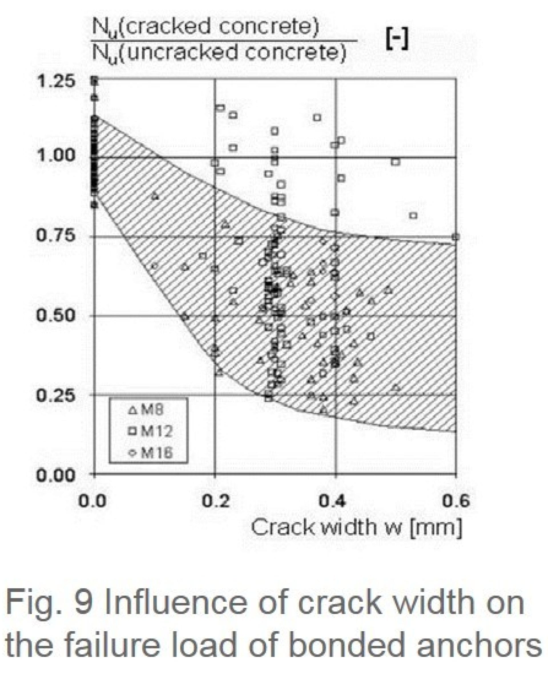
Fig. 9 show presents the ratio of tension failure loads for bonded anchors tested in cracks to their mean capacity in non-cracked concrete, plotted as a function of crack width [1]. The tests were conducted using both, capsule type anchors and injection systems and various mortar types. The anchors were installed in hairline cracks that were subsequently opened to the desire with. The anchors were then loaded to failure with cracks open while pullout failure occurred.


Pullout failure is usually a consequence of loss of bond between mortar and drilled hole, although with some systems the bond between mortar and anchor rod may fail. The scatter of the results of tests in cracked concrete are rather large due to the fact that all kind of mortar types were used and it was not distinguished between the individual behavior of the mortars. If the results are taken together, the anchor capacity in cracked concrete with a crack width of w= 0.3mm to 0.4mm is about 25% to 80% of the values valid for non-cracked concrete. On average the ratio is about 50%.

Please enter alternative text here (optional)

In contrary to this, tests performed in [6] in cracked concrete with Hilti HIT-RE 500-SD according to the procedure mentioned above showed only a reduction of 25% for the value in non-cracked concrete due to the significantly improved penetration behavior and high material strength of the mortar compared to the systems given in Fig. 9

Note, that the reduction is comparable to the behavior of undercut and expansion anchors.

The reduction of the tension capacity by cracks for bonded anchors systems in case of pullout failure can be explained as follows. Owing to the high tensile strength of the mortar, crack opening after anchor installation results in a redirection of the crack around the anchor along the interface between mortar and concrete, effectively causing bond loss on one side of the anchor.

Please enter alternative text here (optional)

Assuming that the crack trajectory as shown in Fig. 10 occurs over the full embedment depth, the bond capacity is theoretically 50% of the capacity in non-cracked concrete. Investigations in [6] indicated that this assumption is not generally valid. 

Using Hilti HIT-RE 500-SD shows significant less bond loss compared to other mortar types (~25% on one side). This is mainly based on the fact that the mortar system influences the crack trajectory compared to the crack trajectory given in Fig. 10 due to its penetration behavior into the pores of the concrete.
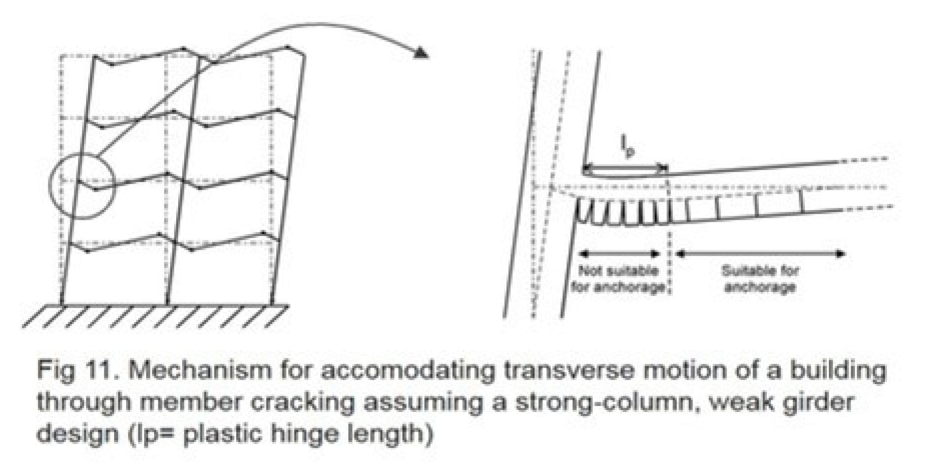
As a structure responds to earthquake ground motion (seismic event) it experiences displacement and consequently deformation of its individual members. This deformation leads to the formation and opening of cracks in members (Fig. 11). 

Consequently all anchorages intended to transfer earthquake loads should be suitable for use in cracked concrete and their design should be predicted on the assumption that cracks in the concrete will cycle open and closed for the duration of strong ground motion. 

During large earthquakes, parts of the structures may be subjected to extreme inelastic deformation. In the reinforced areas yielding of the reinforcement and cycling of cracks may result in cracks width of several millimeters, particularly in regions of plastic hinges [5]. 

Qualification procedures for anchors do not currently anticipate such large crack widths. For this reason, anchorages in this region where plastic hinging is expected to occur, such as the base of shear wall, joint regions of frames, spandrel beams, should be avoided unless suitable design measures are taken [1].

Please enter alternative text here (optional)

[1] Eligehausen R.; Mallee, R.; Silva, J.F. (2006): Anchorage in Concrete construction, Ernst & Sohn, Berlin 2006

[2] Schiessl, P. (1986): Crack influence of the durability of reinforced and prestressed concrete components. Schriftenreihe des Deutschen Ausschuss für Stahlbeton, No. 370, Ernst & Sohn, Berlin 1986 (in German)

[3] Bergmeister, K. (1988): Stochastic in fixing technology based on realistic influenced parameters, Doctor Thesis, University of Innsbruck, 1988 (in German)

[4] Eligehausen, R.; Bozenhardt, A. (1989): Crack widths as measured in actual  structures and conclusions for the testing of fastening elements. Report No. 1/42- 89/9, Institute of Construction Materials, University of Stuttgart, August 1989

[5] Höhler, M, S. (2006): Behavior and testing of fastenings to concrete for use in seismic applications, Doctor Thesis, University of Stuttgart, 2006

[6] Appl, J. (2008): Load bearing behavior of bonded anchors under tension loading, Doctor Thesis, University of Stuttgart, 2008


Ask our engineers