
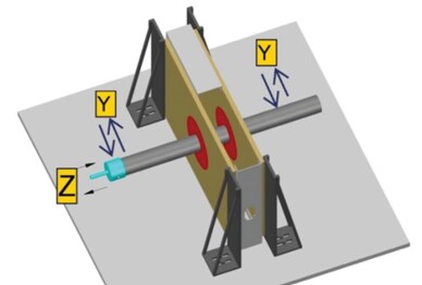
Through Penetration Firestop Systems Tested to Withstand Movement

Figure 1 : Movement test setup for penetration system
Movement in buildings occurs due to various factors such as seismic activity, thermal cycling, hydraulic shock, wind loads, vibrations, live load of slabs, deflection of services, etc. Building Movement can cause failure of penetration and linear joint firestop systems by developing cracks and gaps in the assembly. For instance, the building with high susceptibility to vibrations develop cracks in the structure and by extrapolation, develops cracks and movement in firestop assemblies.
The Evolution of Standards
Joints by design are supposed to accommodate various movements induced by the reasons mentioned above. ASTM E1966 began to acknowledge this impact and added testing methods for movement capabilities of linear joints.
Initially for penetration systems, standards like ASTM E814 assumed a firestop system to be rigid, with no movement. However, this assumption has been challenged and revised over time. In 2016, ASTM E3037 was issued. This addresses the “Test Method for Measuring Relative Movement Capabilities of Through-Penetration Firestop Systems”.
HILTI acknowledges the impact of movement in both penetration and joint systems and performs internal testing at its in-house testing facility for its portfolio for joint systems as well as penetration system. Both firestop systems are tested by cycling a certain number of times to achieve certain displacement. The systems are tested by a combination of both perpendicular and parallel directions, to represent movement that can be experienced over a building’s lifetime. Each cycle and distance are tracked until a maximum movement capability is attained. The system is then subjected to a fire test to ensure the firestop system will perform as intended in the event of a fire, even after being subjected to movement.
Figure 2 : Simplified example of movement test assembly for penetration
Identifying Movement Capabilities
For penetrations, the movement range categories for the Y** direction (perpendicular to the penetrant) are (up to) 5%, 25%, 50% and 100% of the annular space, and for the Z** direction (parallel to the penetrant) (up to) .25”, .5”, 1”, 3.21”.
For joints, the movement capability ranges for different causes are true only if the system withstand cycling as per the following table.
It’s important to note that a system cannot be certified for movement alone and must also pass the fire test. These results quantify the amount of movement firestop systems can accommodate while still performing as intended in the event of a fire.
Research and Testing
Hilti has successfully tested a variety of penetration and linear joint systems, from those that use sealants, such as FS-ONE Max, to those that use pre-formed devices, such as the CP 653 speed sleeve or CFS-BL firestop blocks. Through intense movement criteria
research and testing, Hilti has determined that pre-formed devices, such as CP 680 cast-in device, CFS-BL firestop blocks and CP 653 speed sleeve perform significantly better when it comes to movement than traditional sealant systems (refer to table below for testing results). The preformed devices typically exceed the limit thresholds set by the standards, and as a result, for firestop systems where movement is critical, these devices would be recommended. Some firestop devices, for example, allow up to 100% movement in Y direction and the highest performance in Z direction like CP 680, CP 653 etc. (refer to table below).
Figure 3 : Test results of firestop solutions for movement - preformed devices
Figure 4 : Test results of firestop solutions for movement - sealants
Additional Attributes
These products also provide multiple additional attributes like acoustic insulation, air and gas tightness, water resistance, etc. to serve multiple needs of different stakeholders. These attributes, together with the fulfillment of movement criteria described help make buildings more resilient. In addition, HILTI can be a great partner to collaborate with to achieve Sustainability Goals as we help you achieve Green Building Certification through VOC certificates, Material Health Certificates, Product Carbon Footprint and Environmental
Product Declarations.
Conclusion
One should not take movement capability* data as a single/only parameter for firestop selection. It is advised to check other parameters like seismic study, climatic conditions at site, required fire rating, type of penetrant and penetrating items etc. and select the most
optimal firestop solution with Hilti. This comprehensive approach ensures the safety and longevity of the building structure, considering the dynamic nature of building movements.
Also, make sure the solution installed in a joint system could accommodate sufficient joint compression, joint extension, or both, as compared to the compression or extension expected of the joint. Most of the joints in buildings will experience both extension and
compression over time, but some listed joint systems are for compression only. These may therefore be inadequate and should be avoided.
* Movement capability is the max. amount of movement, the joint seal can tolerate as statedby manufacturer, expressed as a percentage** of the nominal width.
** The percentage is the displacement in one direction i.e. for lateral movement either elongation (+x%) or compression (-x%).
X = vertical movement, up and down,
Y = horizontal movement, left and right, perpendicular to the penetrant
Z = axial movement, in and out, parallel to the penetrant
For more information, please contact your local Hilti experts or go to Hilti's online shop.
I. For information on other additional attributes, check out our Engineering Centre article OR check out the video:
Overview of the secondary attributes of firestop - Top & Bottom of Wall
II. To understand better about movement in building construction, check out the video: Overview of movement in firestop with Hilti
DOWNLOAD INSPECTION GUIDEBOOK FOR FIRE PROTECTION INSTALLATION FROM HERE
References:
1. ASTM E3037-20
2. ASTM E1966
In case you need more support on this topic, please leave a comment on this article or post your question in our Engineering Centre
For further enquiry or clarifications, please feel free to reach out to us at my.engineering@hilti.com